
Beyond the Figure 6: Advanced Bolt-Hole Inspection with the NORTEC 700i
For decades, rotary eddy current inspection of aircraft fastener holes has been one of the most effective applications of eddy current testing.
The basic concept hasn’t changed much.
Remove the fastener. Insert a rotating probe into the hole. Move the probe through the thickness of the structure and look for the characteristic response from a crack intersecting the bore of the hole.
Anyone who has performed a lot of bolt-hole inspections is probably familiar with the traditional Figure 6 display. It works—and it has worked very well for a long time.
But the NORTEC 700i adds something interesting to the process.
Instead of treating the rotary signal as something that simply flashes across the screen as the probe passes a crack, the instrument can acquire the inspection and display the indication in several different ways.
That changes how we can look at bolt-hole data.
The Traditional Figure 6 Is Still There
Evident hasn’t thrown away the traditional approach.
The NORTEC 700i includes a Figure 6 application preset specifically for bolt-hole inspection. In the procedure described in the owner’s manual, connecting the 700i to the MiniMite scanner activates the bolt-hole use case through the instrument’s PowerLink function. The operator then selects the Figure 6 preset, which loads the inspection configuration.
Calibration will also look familiar to an experienced aerospace ET technician.
Using a reference standard containing an EDM notch, the operator adjusts angle and gain so the notch response is vertically oriented on the XY display and reaches 100% full-screen height on the Y(t) display. The synchronization angle is then adjusted to center the signal on the Y(t) view, followed by an additional 6 dB of gain in the manual’s example procedure.
So far, this is recognizable rotary eddy current testing.
But this is where the 700i gets more interesting.
The Instrument Can Acquire the Entire Bolt-Hole Scan
One of the biggest differences is that the operator isn’t limited to watching a live trace while pulling the probe through the hole.
The manual describes a Bolt Hole Acquisition function. The probe is nulled in air, the entire length of the hole is scanned, and the acquisition is then frozen for examination.
Think about the practical significance of that.
Traditional rotary inspection places a lot of emphasis on the technician recognizing an indication while the probe is moving. With acquired data, the inspection becomes something that can also be reviewed after the scan.
For aerospace work, where bolt holes may pass through several structural layers, that is potentially very useful.
Instead of asking only:
“Did I see a crack signal?”
we can begin asking:
“Where in the hole did that signal occur?”
And that brings us to what I think is one of the most interesting features.
You Can Select an Indication From the C-Scan
After acquiring the hole, the NORTEC 700i allows the operator to use an index cursor to select an indication directly from the C-scan.
That’s a significant departure from the way many technicians think about conventional rotary bolt-hole ET.
We normally associate C-scans with encoded inspections, eddy current arrays, ultrasonic testing, or other data-acquisition techniques.
But here we’re applying that type of visualization to a conventional rotating bolt-hole probe.
The scanner provides the rotational component while the technician moves the probe through the hole. The instrument can then organize that information spatially.
The result is much more intuitive than trying to mentally reconstruct the location of an indication from a rapidly moving Figure 6 alone.
Where Is the Crack Around the Hole?
Once an indication is selected, the NORTEC 700i provides a Defect view showing its position in the bolt hole relative to scanner orientation.
That is an important piece of information.
A rotary probe inherently contains circumferential information because the coil is rotating through 360 degrees. Historically, much of that positional information wasn’t necessarily presented to the technician in an intuitive graphical form.
The 700i can turn that rotational information into a representation of where around the circumference of the hole the indication occurred.
For an aerospace inspector, that’s immediately useful.
Instead of simply:
“There is an indication in this hole.”
we can potentially understand:
“There is an indication at this circumferential position in the hole.”
That can make subsequent investigation much easier.
Which Layer Is It In?
This may be even more valuable.
Aircraft structures frequently aren’t a single piece of aluminum. A fastener may pass through multiple skins, doublers, straps, fittings, or other structural members.
Finding an indication is one thing.
Determining which layer contains it can be another.
According to the NORTEC 700 manual, the bolt-hole C-scan provides the indication’s position on the strip chart as well as the layer containing the defect.
That is a very useful way of presenting rotary bolt-hole data.
The technician can now correlate the indication with its position through the thickness of the stack rather than relying entirely on probe position and operator interpretation during the live scan.
For multilayer aerospace structures, that’s a substantial improvement in visualization.
And We Still Have the Impedance Plane
None of these displays eliminate traditional eddy current signal analysis.
The NORTEC 700i also provides the familiar XY view, where the selected defect can be evaluated in terms of its phase and amplitude.
That is important.
The advanced displays shouldn’t replace understanding the eddy current signal. They supplement it.
An experienced technician still wants to know:
What does the signal look like?
What is its amplitude?
What is its phase response?
Does it behave like the calibration notch?
Is it repeatable?
Is there evidence that the response is geometric, metallurgical, or actually flaw-related?
The graphical displays provide additional context, but the underlying eddy current response remains important.
Four Ways of Looking at the Same Inspection
This is probably the feature I find most interesting about the NORTEC 700i bolt-hole application.
The manual provides an alternate DV & Y-t & C & XY layout.
In other words, we’re no longer restricted to one representation of the signal.
We can look at the inspection from several perspectives:
- Y(t)/strip-chart-type information — where the indication occurred as the probe traveled through the hole.
- C-scan — spatial information that helps locate the indication and identify the affected layer.
- Defect View — circumferential position around the bolt hole.
- XY impedance-plane view — traditional phase and amplitude information.
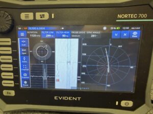
That is where the real value lies.
The instrument isn’t necessarily giving us four different inspections. It is giving us four different ways of looking at the same eddy current information.
For an experienced Level II or Level III, that distinction matters.
The Probe Is Still Doing Conventional Eddy Current Testing
It’s also worth emphasizing that the physics haven’t suddenly changed.
In the manual’s example, the bolt-hole probe is a self-adjusting/self-expanding rotary hole probe with a reflection-differential coil configuration, 0.437 inch (11.11 mm) in diameter, with a specified operating frequency range of 200 kHz to 3 MHz.
The rotating coil still passes close to the bore surface.
A crack disturbs the induced eddy-current flow.
The coil detects the resulting electromagnetic change.
What has evolved is the acquisition, synchronization, encoding, processing, and presentation of that signal.
And that distinction is important because sometimes we get so caught up in new displays that we assume we’re looking at a new inspection technology.
We’re not.
We’re looking at a much more sophisticated way of extracting and presenting information from a proven inspection technique.
Why This Matters in Aerospace
Bolt holes are particularly well suited for this kind of visualization.
Fatigue cracking associated with fastener holes is often highly localized, and the structure may contain several layers. The technician is therefore interested in more than simple detection.
Ideally, we want to know:
Is there an indication? Where through the stack is it? Where around the circumference is it? And what does the actual eddy current response look like?
The NORTEC 700i gives the technician tools to answer all four questions from the same acquired scan.
That doesn’t make calibration standards, procedures, probe selection, technician qualification, or good ET fundamentals any less important.
In fact, the manufacturer specifically cautions that the examples in the manual are teaching aids and that inspection techniques and procedures require independent verification for the particular application—especially as application criticality increases.
That’s particularly relevant in aviation, where an instrument feature should never be confused with an approved inspection procedure.
The Bigger Picture
I have used enough generations of eddy current equipment to appreciate what has really changed over the years.
The fundamental electromagnetic principles haven’t changed.
A crack still disrupts eddy-current flow.
Probe design still matters.
Frequency still matters.
Fill and probe-to-hole coupling still matter.
Calibration still matters.
And the inspector still needs to understand what a legitimate flaw response looks like.
What has changed dramatically is what we can do with the signal after we acquire it.
The NORTEC 700i bolt-hole application is a good example.
The traditional Figure 6 hasn’t disappeared. Instead, it has become one view within a much richer inspection environment.
Figure 6 tells you something happened.
The additional displays can help you understand where it happened.
And for multilayer aerospace bolt-hole inspection, that is a pretty significant advancement.