
If you’re testing carbon steel or any ferromagnetic material with eddy currents, you’ve probably heard this advice:
“Use higher frequencies for better surface flaw sensitivity.”
It sounds reasonable. After all, higher frequencies produce stronger eddy current signals, and the shallow penetration helps zero in on surface-breaking defects.
But in real-world steel testing, this approach can backfire.
In fact, some of the clearest flaw signals actually show up at lower test frequencies.
The Hidden Problem: Directional Noise
Ferromagnetic materials like carbon steel come with built-in complications:
-
High magnetic permeability pushes eddy currents to the surface—even at low frequencies.
-
But microstructural variation (stress, grain structure, heat treatment) causes strong noise signals on your impedance display.
-
This noise often mimics or overwhelms real flaw indications.
What matters isn’t just how strong your signal is—it’s whether you can separate it directionally from all that background interference.
The Real Goal: Signal Direction, Not Just Amplitude
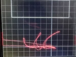
When viewed in the impedance plane (phase display), different influences point in different directions:
-
Crack signals point one way.
-
Lift-off, diameter variation, and permeability noise point another.
The farther apart those directions are, the easier it is to identify real flaws.
-
Moderate signal amplitude
-
Excellent directional separation (think F90)
-
Crack signal is “orthogonally separated” from the noise
-
Ideal for phase discrimination
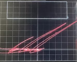
2 MHz
-
Stronger overall signal amplitude
-
But… the there is less phase separation between probe motion and flaw signals
-
Smaller flaws may be harder to distinguish from background noise
👉 In short: Bigger is not always better.
So How Do You Pick the Right Frequency?
Forget the math. Nobody’s calculating “limit frequency” in the field anymore. Here’s the method that works:
-
Use a calibration standard with known cracks
-
Try a range of frequencies — low, medium, high
-
Watch both the size of the signal and the angle it makes on your instrument
-
Pick the frequency where:
-
The crack signal is strong
-
And clearly points in a different direction than the noise
-
🎯 That’s your sweet spot.
What Förster Figured Out (and Why It Still Applies)
Back in the 1940s, Dr. Förster developed a mathematical model explaining exactly this behavior. His Figure 23 showed that in ferromagnetic materials, the best flaw discrimination (again, think F90) happens at moderate frequencies, where crack signals are most separated from background effects in the impedance plane.
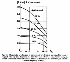
You don’t need to calculate anything—just watch what your scope is telling you. If your instrument shows the flaw signal turning away from the lift-off/permeability direction, you’ve found the right setup.
Final Takeaway
When testing steel:
-
Higher frequencies give bigger signals, yes
-
But bigger isn’t always better
-
Your goal is signal clarity, not just signal size
-
Look for the frequency where cracks stand out by direction, not just amplitude
With ferromagnetic materials, finding the sweet spot beats chasing the strongest signal every time.
Part of a Series: Förster Impedance Graphs—Cracking the Code
This blog is part of my ongoing series exploring Förster impedance diagrams—how to read them, apply them, and translate their theory into practical test setups. If you’re a serious eddy current tech, understanding these signal direction patterns will change how you use your scope.
Learn More at eddycurrent.com
Want more real-world insights, historical context, and hands-on eddy current guidance? Visit eddycurrent.com — a dedicated resource for technicians, trainers, and NDT professionals. No sales pitches, just solid information.