
Many eddy current technicians memorize formulas during Level I and II training without ever being shown how those formulas connect together in the real world.
One of the best examples is the relationship between:
- inductance
- inductive reactance
- and coil merit
These concepts are not just academic electrical theory.
They explain why:
- one probe is noisy while another is stable
- certain frequencies produce better flaw separation
- some probes feel “sharp” and responsive
- and why probe design matters so much in Eddy Current Testing (ECT).
Understanding these relationships helps technicians move beyond simply following procedures and toward actually understanding the behavior of the probe itself.
The Coil Is the Heart of Eddy Current Testing
At its core, an eddy current probe is simply an electromagnetic coil.
When alternating current flows through that coil, it creates a changing magnetic field.
That magnetic field interacts with the test material and produces eddy currents.
The entire inspection depends on how efficiently the coil generates and responds to those electromagnetic interactions.
That is where inductance enters the picture.
What Is Inductance?
Inductance is the property of a coil that resists changes in current flow by storing energy in a magnetic field.
A coil with higher inductance stores magnetic energy more effectively.
One simplified formula for inductance is Wheeler’s Formula for an air-core circular coil:
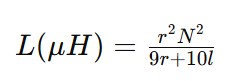
Where:
- L = inductance in microhenries
- r = coil radius
- N = number of turns
- l= coil length
This formula reveals several extremely important concepts for eddy current technicians.
More Turns = More Inductance
Notice that the number of turns is squared.
That means:
- doubling the turns dramatically increases inductance
This is why:
- high-turn coils often produce strong signals
- small rotating probes may use fewer turns
- probe geometry changes coil behavior
But there is a tradeoff.
More turns also increase resistance.
That becomes important when discussing coil merit.
Inductance Alone Does Not Tell the Whole Story
A coil does not simply possess inductance.
It also possesses resistance.
Resistance wastes energy as heat.
Inductance stores energy magnetically.
The balance between those two properties determines how “good” the coil behaves electrically.
This leads directly to inductive reactance.
Inductive Reactance
Inductive reactance is the opposition a coil presents to alternating current due to its inductance.
The formula is:
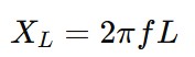
Where:
- f= frequency
- L = inductance
This formula explains why frequency is so important in ECT.
As frequency increases:
- inductive reactance increases
As inductance increases:
- inductive reactance also increases
This is why the same probe can behave completely differently at different test frequencies.
Why Frequency Changes Probe Behavior
At low frequencies:
- the coil behaves less inductively
- resistance becomes more dominant
At higher frequencies:
- the inductive portion of the coil dominates
This affects:
- phase angle
- sensitivity
- penetration depth
- signal stability
- flaw response
A technician may notice that:
- one frequency produces cleaner flaw separation
- another frequency produces excessive lift-off noise
- or another frequency produces unstable phase rotation
These effects are tied directly to inductive reactance.
Coil Merit: The Relationship Between XL and R
Now we arrive at coil merit.
Coil merit is commonly expressed as:

Where:
- XL= inductive reactance
- R = resistance
This ratio describes how efficiently the coil behaves as an inductor versus how much energy is wasted through resistance.
A high-merit coil:
- behaves more like a pure inductor
- produces cleaner signals
- often provides better sensitivity
- tends to have better signal-to-noise characteristics
A low-merit coil:
- behaves more resistively
- may appear noisy or muddy
- can suffer reduced phase stability
Why This Matters in Eddy Current Testing
This is not just electrical engineering theory.
It affects real inspections every day.
For example:
- array probes
- rotating probes
- bobbin coils
- conductivity probes
- surface probes
all rely on balancing:
- inductance
- resistance
- operating frequency
- coil geometry
Probe designers constantly make compromises.
A coil with extremely high inductance may:
- become frequency limited
- suffer reduced bandwidth
- become physically impractical
A coil with very low resistance may:
- require larger wire
- increase probe size
- reduce spatial resolution
Everything is connected.
Troubleshooting Through Understanding
A technician who understands these relationships can troubleshoot more intelligently.
Instead of saying:
“This probe feels weak.”
They may begin asking:
- Did the inductance change?
- Is resistance increasing?
- Is the cable damaged?
- Is a winding partially shorted?
- Is the operating frequency appropriate?
That is a completely different level of technical thinking.
The Bigger Picture
Many technicians learn how to:
- set up equipment
- perform a calibration
- detect discontinuities
Fewer understand why the probe behaves the way it does.
But understanding:
- inductance
- inductive reactance
- and coil merit
helps explain the electromagnetic foundation of Eddy Current Testing itself.
The technician begins seeing the probe not as a mysterious black box…
…but as a dynamic electromagnetic system whose behavior can be predicted, understood, and optimized.
That is where real eddy current expertise begins.
Learn More About Eddy Current Testing
For more articles, training resources, historical research, formulas, calculators, and educational material related to Eddy Current Testing, visit: