
Remote Field Testing (RFT) Sizing of Support Plate Fretting Wear
Why Conventional Eddy Current and Partial Saturation Fall Short in Carbon Steel Tubing
Support plate fretting wear is not a new problem.
It has long been recognized as one of the leading causes of heat exchanger tube degradation — second only to corrosion in many systems.
But what makes fretting uniquely frustrating is this:
It occurs at support plate locations — exactly where signal interference is most severe.
The 1997 Materials Evaluation paper by Shatat and Atherton examined whether remote field testing (RFT) could not only detect fretting under carbon steel support plates — but actually size it.
The findings are still highly relevant today.
- Understanding Remote Field Energy Coupling
Before discussing fretting, we need to revisit the physics of remote field testing.
In RFT, the exciter and detector are typically spaced 2.5–3 pipe diameters apart. At this spacing, the dominant coupling path is no longer internal — it is external.
Energy travels:
- Outward through the pipe wall
- Along the outside surface
- Back inward through the wall to the detector
This two-wall transit is what gives RFT its through-wall sensitivity.
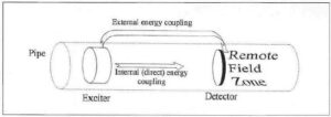
Figure 1 – Remote field energy coupling paths. In the remote field zone, external coupling dominates and enables through-wall sensitivity.
This external path is also the source of the support plate problem.
Because the support plate sits directly in that external energy path.
- Why Conventional Eddy Current Cannot Mix Out Carbon Steel Support Signals
Now let’s address something that’s often misunderstood.
In nonmagnetic tubing (Inconel, stainless steel), conventional eddy current uses multi-frequency mixing to suppress support plate signals.
Why does that work?
Because support plates in those systems primarily introduce conductivity and geometric effects. The signals are relatively linear and can be phase-rotated and subtracted.
But carbon steel tubing is different.
Ferromagnetic tubing introduces:
- High relative permeability
- Nonlinear B-H behavior
- Strong magnetic field distortion
- Complex flux redistribution
- Frequency-dependent permeability effects
In remote field inspection of ferromagnetic tubes:
- The support plate is also ferromagnetic.
- The plate and tube interact magnetically.
- The air gap between them funnels flux.
- The field behavior is governed by skin depth and permeability — not just conductivity.
This produces a support plate signal that is not a simple additive component.
It is a redistribution of the entire external field structure.
Conventional eddy current mixing assumes:
Signal_total = defect + support + noise
But in carbon steel RFEC:
Signal_total ≠ simple superposition
The support plate changes the field geometry itself.
You cannot “mix it out” cleanly.
- Why Partial Saturation Techniques Also Fall Short
Partial saturation attempts to reduce permeability effects by biasing the tube toward magnetic saturation.
This works moderately well for:
- Removing lift-off variations
- Stabilizing permeability in some cases
But under support plates:
- The plate remains ferromagnetic.
- The air gap still exists.
- Flux funneling still occurs.
- Field redistribution remains nonlinear.
- Complete saturation is rarely achieved uniformly.
Even if the tube approaches saturation locally, the plate and gap geometry still alter the remote field path.
You are not just changing permeability.
You are altering the boundary conditions of the electromagnetic system.
That cannot be solved with simple mixing.
- The Characteristic Support Plate Signature
The paper shows that support plates produce a distinctive voltage-plane signature.
On the voltage plane:
- A long tail appears as the probe approaches
- A slight amplitude increase occurs before the plate
- A sharp drop occurs when transmitter and receiver are separated
- The trace forms a characteristic loop.
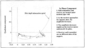
Figure 2 – Calculated voltage-plane response of a support plate. Note the long tail and characteristic amplitude behavior.
This signature is not random.
It is physics-driven.
- The Physics Behind the Signature: Energy Funneling
Using finite element modeling (~9,500 elements), the authors examined energy flow via the time-averaged Poynting vector.
They found:
Energy funnels through the air gap between pipe and plate.
Because:
- Both pipe and plate are ferromagnetic
- The air gap creates a large permeability contrast
- Magnetic field intensity increases in the gap
- Energy density concentrates there
This explains the amplitude bump before the plate.
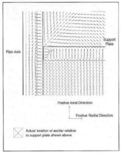
Figure 3 – Time-averaged Poynting vector at the pipe-plate interface. Energy funnels through the air gap, explaining support plate signal behavior.
This is not a simple interference.
It is a redistribution of electromagnetic energy.
That is why conventional mixing fails.
- The Breakthrough: Multi-Frequency Phase Slope
Instead of trying to subtract the plate signal, the authors examined phase behavior under the plate.
They plotted detector phase versus √frequency.
They discovered:
- Phase follows the skin depth relationship.
- The slope is proportional to remaining wall thickness.
- The slope does not change due to the presence of the support plate.
That last point is critical.
The support plate distorts amplitude and absolute phase.
But the phase-frequency slope remains stable.
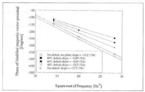
Figure 4 – Detector phase versus √frequency under support plate. The slope remains predictable and follows skin-depth physics.
This allows sizing without knowing nominal full-wall phase.
- Experimental Validation
The authors built a mockup:
- 6.4 mm thick support plate
- 19 mm OD carbon steel pipe
- 37% and 81% full circumferential grooves
They measured slopes:
- No plate: −19.8°/√Hz
- Under plate full wall: −20.0°/√Hz
- Defects changed slope significantly.
Depth estimates were within ~10% of actual wall thickness.
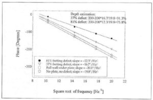
Figure 5 – Experimental verification of fretting depth estimation under support plate.
This confirms that slope-based multi-frequency sizing works — even under ferromagnetic support plates.
- Practical Implications for Today’s Inspections
For carbon steel heat exchanger tubing:
✔ Conventional eddy current mixing cannot adequately suppress support signals.
✔ Partial saturation cannot eliminate geometric field redistribution.
✔ Remote field must be analyzed using phase behavior, not amplitude alone.
✔ Multi-frequency slope analysis provides a physics-based sizing method.
The takeaway:
Do not attempt to “mix out” carbon steel support plate signals as if they behave like nonmagnetic systems.
They don’t.
Understand the field.
Measure the slope.
Respect the physics.
Final Thought
In ferromagnetic tubing, support plates are not noise.
They are part of the electromagnetic boundary condition.
The sooner we treat them that way, the more accurate our inspections become.
For deeper resources on remote field theory, skin depth behavior, and electromagnetic analysis in ferromagnetic materials, explore:
👉 eddycurrent.com
Because this isn’t black magic.
It’s Maxwell’s equations in action.